![]()
Dimensional
Overview
Functional Descriptions
HSI-24
HSU-128
System Specifications
HSI-24
HSU-128
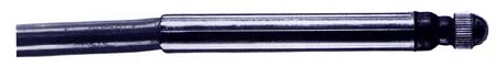
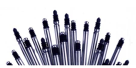
Probes
Probes List
Features
4001
0.8mm/32mil
4002
1.5mm/60mil
4004
3.0mm/120mil
4010-0 0.5mm/20mil
4010-1 0.5mm/20mil
4010-2 0.5mm/20mil
4012
2.0mm/80mil
Spare Parts
Probes for IQS Wheel System
Signal Conditioner for
IQS Wheel System
Strain/Pressure
HSS-10
System Specifications
HSS-10
Customizing
Software
Applications
Probe Attachments
Cable Modifications
Software/
Documentation
Downloads
HSI-24
Manuals
HSI-24 Drivers & Libraries
HSI-24 App Program
HSU-128 Manuals
HSU-128 Drivers & Libraries
HSU-128 App Program
HSS-10 Software
Software/
Documentation
Downloads
HSP-8 Drivers & Libraries
HSP-8 App Program
Miscellaneous
About the
Company
Table of contents

We are dedicated to the satisfaction of our customers
providing Probe Products signal conditioners, Nairda
probes
and solutions to all their measurement needs.
![]()
HSS-10 Software
Software available for OEM customers include the following:
| Drivers in C | |
| Drivers in Pascal | |
| Drivers in Basic | |
| 16 Bit DLL | |
| 32 Bit DLL |
END USER Software
Demonstration/Setup Software is available upon request for the HSS-10.
The software interface for the HSS-10 is essentially identical to that of the HSI-24.
The strain gauge signals may be accessed by using the name S1 through S10 in HSI-24 style channel
formulae. These strain gauge signal names can be used in formulae in the same manner as HSI-24
T1 through T24 access LVDT signals.
![]()
A number of new commands have been added to accommodate the strain gauge inputs.
These include the following:
![]()
Set strain FSV - This allows the scaling of the strain gauge output numbers into
convenient engineering units.
// INPUT:
// int strain - strain gage number 1 to 40
// float *tfsv - pointer to an IEEE single precision floating point number
//               which will be set as the full scale value
// OUTPUT:
// returns 0 when command is completed successfully
int set_sfsv(int strain, float *tfsv)
// INPUT:
// int strain - strain gage number 1 to 40
// float *tfsv - pointer to an IEEE single precision floating point variable
//               into which the full scale value will be stored
// OUTPUT:
// returns 0 when command is completed successfully
int read_sfsv(int strain, float *tfsv)
![]()
Set strain zero - This allows for setting a zero offset value. This command sets
an offset value which is added to the output value of the strain
gauge. This offset is in addition to the 'AIN Ratiometric Offset'.
The 'AIN Ratiometric Offset' is performed within the strain gauge
signal conditioning hardware.
// INPUT:
// int strain - strain gage number 1 to 40
// float *szero - pointer to an IEEE single precision floating point number
//               which will be set as the zero value
// OUTPUT:
// returns 0 when command is completed successfully
int set_szero(int strain, float *szero)
// INPUT:
// int strain - strain gage number 1 to 40
// float *szero - pointer to an IEEE single precision floating point variable
//               into which the zero value will be stored
// OUTPUT:
// returns 0 when command is completed successfully
int read_szero(int strain, float *szero)
![]()
Read strain - This command returns the present value of the specified strain gauge
as a floating point number. The value is scaled and offset by the FSV
and Zero for the specified strain gauge. Note that the value still
includes the 'AIN Ratiometric Offset', 'AIN Non-ratiometric Offset',
'VREF Non-ratiometric Offset' and 'Ratiometric Gain' corrections.
// INPUT:
// int strain - strain gage number 1 to 40
// float *value - pointer to an IEEE single precision floating point variable
//               into which the value will be stored
// OUTPUT:
// returns 0 when command is completed successfully
int read_strain(int strain, float *value)
![]()
Read strain direct - Raw unprocessed readings from the strain gauges are
returned as long integers. Note that these 'unprocessed' readings
include the 'AIN Ratiometric Offset', 'AIN Non-ratiometric Offset',
'VREF Non-ratiometric Offset' and 'Ratiometric Gain' corrections, but
do not include the effects of the 'Set strain FSV' and 'Set strain
zero' commands.
// INPUT:
// char *StrainList - pointer to list of one byte numbers which are the
//               strain gage numbers to be read. Each is a number from 0 to 39.
// long **values - pointer to an long integer pointer variable which will be set
//               to point to the start of the list of long integers which
//               are the values of the requested strain gages.
// OUTPUT:
// returns 0 when command is completed successfully
int read_strain_direct(char *StrainList, long **values)
Calibration/Setup/Maintenance Commands
Set Strain Configuration - This command is normally used during system
configuration to setup the features of each of the strain gage signal conditioners.
Each of the up to 40 signal conditioners may be setup differently without affecting
other channels. The Gain and Unipolar settings combine to produce the following
useable ranges:
Min Scale Mid Scale Max Scale |
Gain Uni/Bi Gage Range Input Adc Input Adc Input Adc |
25 Unipolar 0mv to 200mv 0mv -> 00000 100mv -> 80000 200mv -> FFFFF |
50 Unipolar 0mv to 100mv 0mv -> 00000 50mv -> 80000 100mv -> FFFFF |
100 Unipolar 0mv to 50mv 0mv -> 00000 25mv -> 80000 50mv -> FFFFF |
200 Unipolar 0mv to 25mv 0mv -> 00000 12.5mv -> 80000 25mv -> FFFFF |
25 Bipolar -100mv to +100mv -100mv -> 80000 0mv -> 00000 +100mv -> 7FFFF |
50 Bipolar -50mv to +50mv -50mv -> 80000 0mv -> 00000 +50mv -> 7FFFF |
100 Bipolar -25mv to +25mv -25mv -> 80000 0mv -> 00000 +25mv -> 7FFFF |
200 Bipolar -12.5mv to +12.5mv -12.5mv -> 80000 0mv -> 00000 +12.5mv -> 7FFFF |
// INPUT:
// int strain - strain gage number 1 to 40
// int Freq - select chopping frequency
//            0 : No chopping (DC excitation)
//            1 : 300Hz
//            2 : 600Hz
//            3 : 1200Hz
// int Gain - select Programmable Gain Amplifier gain setting
//            0 : gain = 25
//            1 : gain = 50
//            2 : gain = 100
//            3 : gain = 200
// int Unipolar - select Unipolar/Bipolar mode
//            0 : Bipolar mode selected
//            1 : Unipolar mode selected
// OUTPUT:
// returns 0 when command is completed successfully
int set_strn_cfg(int strain, int Freq, int Gain, int Unipolar)
![]()
Perform Non-ratiometric Offset Calibration - This command computes
values for the 'VREF Non-ratiometric Offset' and 'AIN Non-ratiometric
Offset'.  These offset values correct for errors which would be
produced by offset voltages induced in the signal conditioner to
bridge wiring.  When this command is performed the pair of jumper
plugs for the strain signal conditioner must be moved to the Zero
Excitation position. Once performed the computed offsets can be
stored in non-volatile memory which is contained on the HSS-10.
(There is a command to do this.) After being stored the offsets will
automatically be loaded into the signal conditioner each time the
HSS-10 is powered up.
![]()
Perform Ratiometric Offset Calibration - This command computes a value
for the 'AIN Ratiometric Offset'.  This offset value corrects the
output value to read zero with "zero" weight on the scale platform.
Very large offset amounts can be zeroed without loss of resolution.
Up to +/- 200 percent of full scale can be trimmed from the input
signal. Once performed the computed offsets can be stored in
non-volatile memory which is contained on the HSS-10. (There is a
command to do this.) After being stored the offsets will
automatically be loaded into the signal conditioner each time the
HSS-10 is powered up.
![]()
Perform Gain Calibration - This command computes a value for the 'AIN
Gain'.  The 'AIN Gain' value corrects the output value to read full
scale with the desired full scale weight on the scale platform.
Once performed the computed gain can be stored in non-volatile
memory which is contained on the HSS-10. (There is a command to do
this.) After being stored the gain will automatically be loaded
into the signal conditioner each time the HSS-10 is powered up.